BATDATUNIT01 - Power and data storage
The BATDATUNIT01 is a specialized module shared across the AIRDOS04 and AIRDOS05 series of detectors. Both models are designed for efficiency with the use of modularity: the calibrated sensor is separated from its data storage and power supply functions. These functions are integrated into interchangeable modules, which also act as processor units with firmware, data storage, and power sources.
The separation of the data storage and power supply from the detection part results from a requirement to ease of periodic maintenance of the AIRDOS04 and AIRDOS05 detectors. By compartmentalizing these functions, the detector allows for easier upgrades, maintenance, and customization based on specific user needs or changing technological advancements.
The concept of an interchangeable digital part significantly reduces the maintenance time required to keep the detector operational. Maintenance on-site (such as on-board aircraft) involves swapping the digital part with another unit that is pre-prepared with cleared data storage, updated firmware, and a charged accumulator.
All the firmware for the detector is also located in this digital part (BATDATUNIT). This ensures that firmware updates can be safely prepared out of the experiment site, off the aircraft, so that the time required for regular maintenance is not extended by firmware updates.
Integrated Data Storage and Power Supply: The BATDATUNIT01 has substantial data storage capacity, allowing for data accumulation over prolonged periods. It also includes a built-in power source, which is important for the detector’s long-term autonomous operation, or in cases in environments where external power may not be readily available.
Embedded Processor with Firmware: BATDATUNIT01 contains a microcontroller that controls the entire detector system and peripherals. This processor is loaded with the firmware located also in BATDATUNIT01, ensuring proper detector operation, and can be off-site updated with new features or improvements.
Environmental Sensors: The module is fitted with internal sensors, including a thermometer, hygrometer, and barometer. These sensors provide information on the ambient environment, factors that can be important for more precise data processing.
USB Mass-Storage Interface: For data management, the module is equipped with a USB mass-storage interface, allowing users to easily access and transfer data from the module. This feature makes the process of data retrieval and analysis straightforward and user-friendly.
Modular design: The module is specifically designed for quick installation and removal, without any additional tools. This design ensures that the AIRDOS04 can be maintained and operated with minimal hassle.
BATDATUNIT01-BAT - Integrated battery power source type
The accumulator module of the AIRDOS04 detector offers an integrated energy storage solution. This module is equipped with up to five lithium-ion cells housed in 18650 battery cases, providing a significant power capacity that can sustain the detector’s operation for up to one month. The maximum capacity corresponds to 64 Wh of energy. The exact number of cells and, therefore, capacity could be altered to fit the specific application requirements or restrictions. Contact us to get more details on that topic.
The battery module could be continuously connected to a USB-C power supply, functioning similarly to an Uninterruptible Power Supply (UPS). In scenarios where the external power supply experiences outages, the accumulator module ensures that the detector continues to operate without interruption, maintaining consistent data collection and detector functionality.
The AIRDOS uses the same protection techniques as have been used in SPACEDOS03 on board of ISS. Therefore, each cell in the battery is over-voltage, under-voltage, over-current, and over-temperature protected. It should also be noted that the over-current protection is managed for each cell separately by a non-reversible fuse. That means any uncommon power situation results in the electrical disconnection of the affected cell. This protective action is not user-reversible for safety reasons. Additionally, the cells are mounted in medical equipment-grade cell holders, which ensures that each cell is separated enough to avoid thermal runaway of the battery in case of an internal short circuit of one cell. For that, the worst case there is an over-pressure fuse in each cell cylinder to avoid an explosion. Also, the plastic material used in AIRDOS has reduced toxicity in case of combustion.
BATDATUNIT01-EXT - External power source type
The digital/data module variant is without any lithium accumulators for applications where batteries are not allowed due to safety restrictions. Designed for environments where a continuous external power source is readily available, this module prioritizes data handling and processing capabilities while relying on external power through a USB-C connection.
This module contains the same critical digital components and firmware as BATDATUNIT01-BAT. Its design facilitates efficient data management, allowing for quick data transfer and analysis when connected to a computer or other devices. The absence of an accumulator is useful in cases where you need to put a detector in places where lithium cells are not permitted.
The integrated data storage of the detector is accessible as a mass-storage device via the USB-C interface. This feature provides fast and user-friendly access to the internal storage, without requiring any external memory readers. More information about the initialization of mass-storage mode is written in the “Device operations” part of this manual.
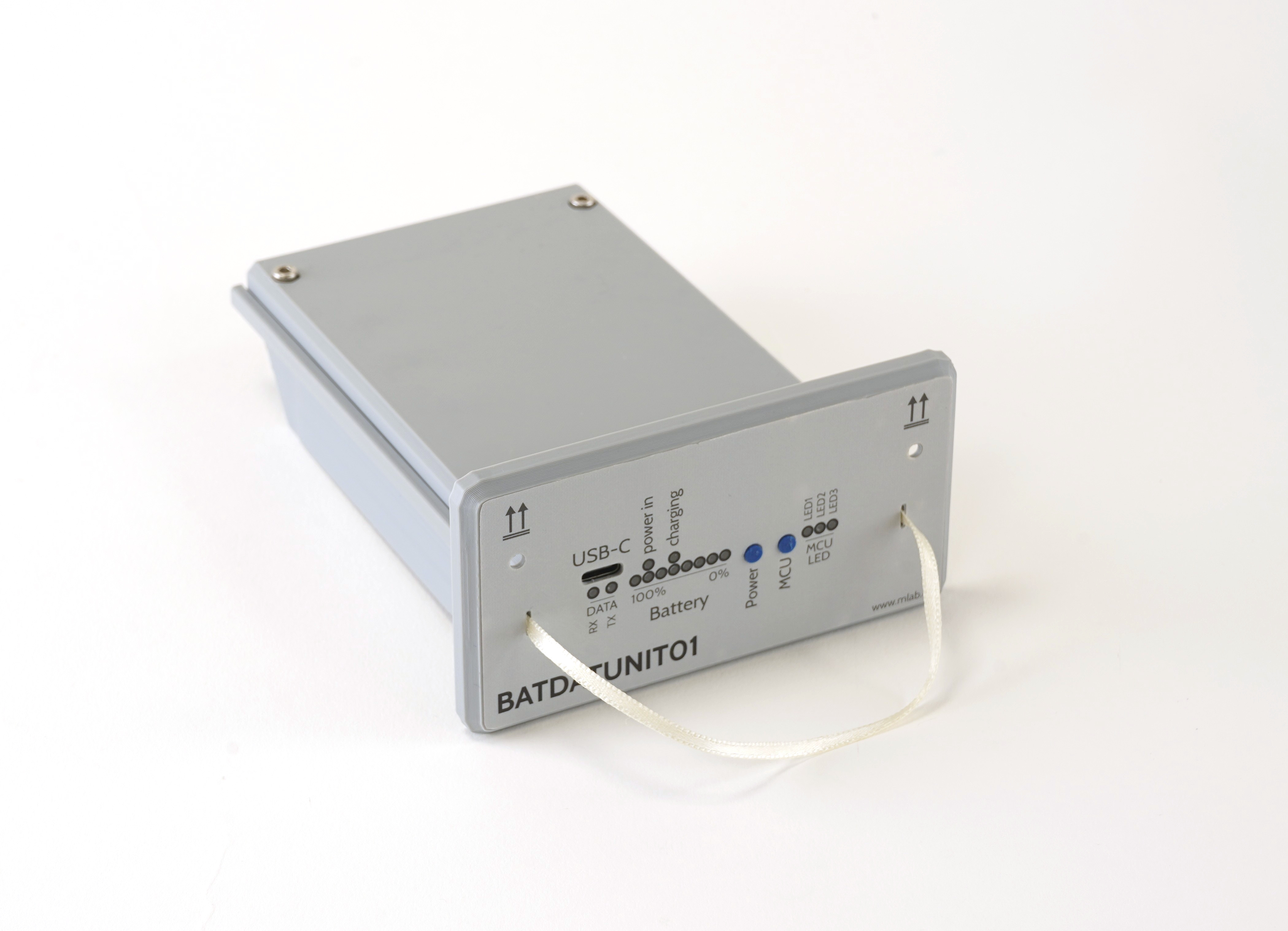
Status indicator description
The front panel of the BATDATUNIT01 module features various indicators and interfaces that provide essential information about the device’s status and functionalities:
- USB-C Port: This is the interface for power input and data communication. When connected to a computer or power source, it facilitates charging the battery and accessing the data storage.
- Power In LED: This LED light indicates when power is being supplied to the module through the USB-C port.
- Charging LED: This LED lights when battery charging is active.
- Battery Level Indicators: A series of LED lights display the current battery charge level. When the ‘Power’ button is pressed, these lights will illuminate to show how much charge remains in the accumulator, ranging from empty (0%) to full (100%).
- Power Button: Pressing this button powers the module on and, with the module running, displays the current battery level using the battery level indicators. Holding this button for more than 10 seconds forces a hardware restart of the device.
- MCU Button: Holding this button powers the module off. LED1, LED2, and LED3 switch off one by one as a roughly three-second countdown; once all three are off, release the button to power the module off (release before the countdown finishes to cancel). Because the button is sampled only once per measurement cycle, in the worst case, it must be held for up to about thirteen seconds before all LEDs are off. A button that stays pressed (stuck or blocked) does not power the module off - the device returns to normal operation after about fifteen seconds. The MCU button also has no effect while USB-C power is connected: the shutdown request is ignored, and the module keeps running, so the USB-C cable must be disconnected before the module can be powered off this way. After a power-off with the MCU button, the device stays off and does not switch back on by itself while inserted; turn it on again with the ‘Power button’ (an approximately one-second hold).
- Data Transmission LEDs (RX/TX): These LEDs indicate active data transmission when the module is connected to a raw data interface, such as a computer. This is not applicable in mass-storage access mode.
- LED Indicators (LED1, LED2, LED3): This set of LEDs indicates the status of the microcontroller unit (MCU), which is the central processor of the module, running the firmware and controlling the device’s operations. These LEDs can be used to indicate specific statuses or alerts as defined by the device’s firmware.
- LED3 (Orange) - Detection exposure is done, writing data to data storage
- LED2 (Red) - It is not possible to write data to internal storage. In the case of this indicator, check the status of integrated mass storage.
- LED1 (green) - mass-storage mode accessible through USB
Firmware update
Both types of BATDATUNIT contain the AIRDOS firmware, shared between AIRDOS04 and AIRDOS05. Updating the firmware of your AIRDOS particle detector is an important process for ensuring the device is equipped with the latest features and any known bugs are solved. The following guide provides a step-by-step approach to updating the firmware using the AVRDUDE tool.
Preparation
- Ensure that your computer is compatible with the AVRDUDE tool.
- Install the AVRDUDE tool, which is available for various operating systems.
- Verify the presence of the AVRDUDE tool in your system by running the command
avrdude -vin the command line. - Obtain the BATDATUNIT01 programming device
Obtaining the Firmware
- Acquire the latest version of the firmware for AIRDOS from the manufacturer. The latest firmware is publicly accessible in the AIRDOS04 repository as a release.
- Before proceeding, make sure you have the correct firmware file for your detector model.
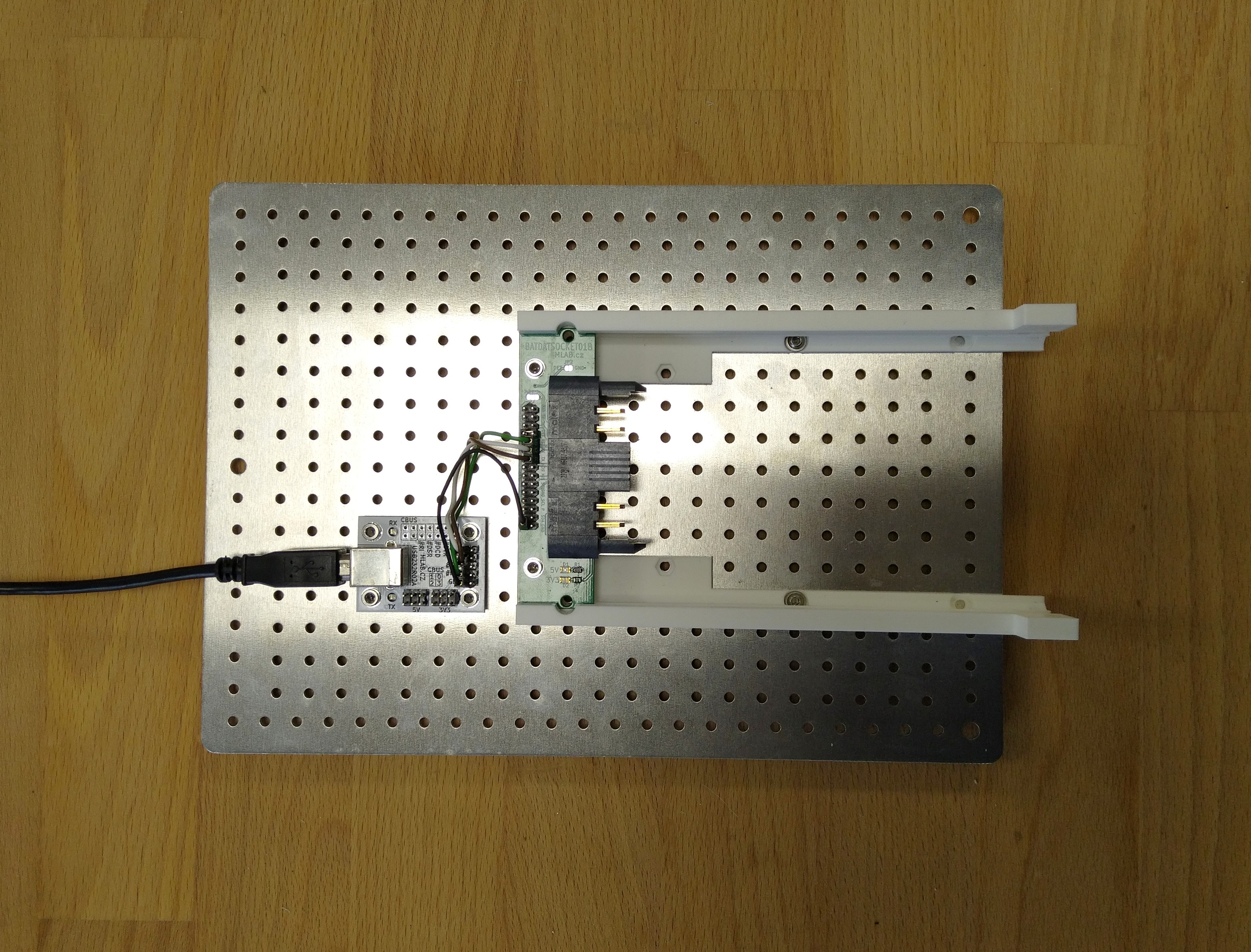
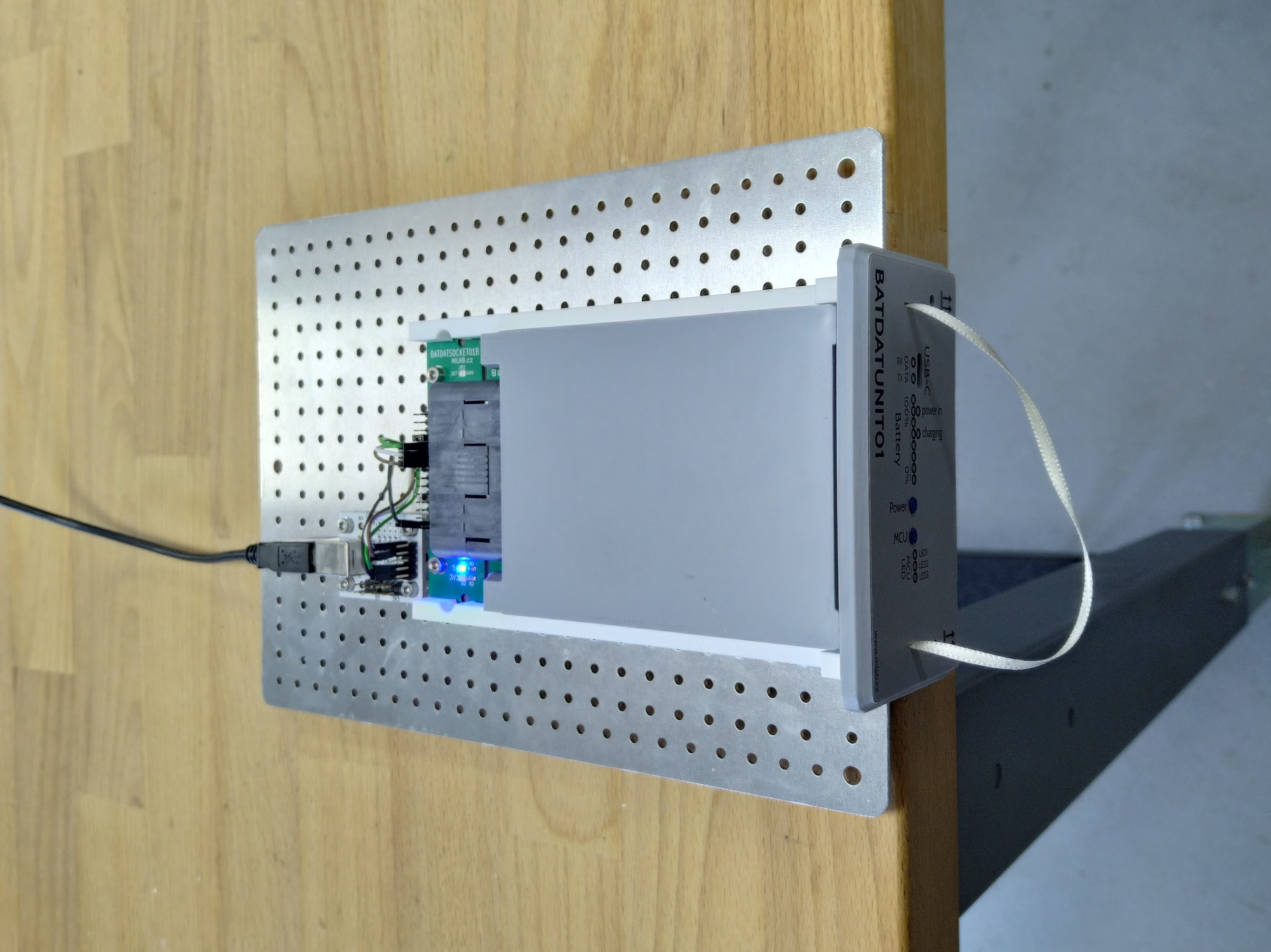
Connecting the Detector
- Connect the programming device to the computer using a USB A-B cable.
- Insert the AIRDOS detector into the slots on the programming device as shown in the following photo
Uploading the Firmware
- Open the command line on your computer.
- Execute the firmware upload using the following command:
avrdude -v -patmega1284p -carduino -P/dev/ttyUSB0 -b57600 -D -Uflash:w:<fw_path>:i
Replace <fw_path> with the path to the downloaded firmware file. Ensure the /dev/ttyUSB0 port matches the port where the programming device is connected.
Verification
- Check that the upload occurred without reported errors.
- After updating the firmware, conduct tests to verify the functionality of the detector and the successful addition of new features or fixes.
When updating the firmware, it is important to follow instructions carefully and be cautious to avoid damaging the equipment. If uncertain or in need of more information, always refer to the manufacturer or consult an expert.